Can Bus Programming Tutorial – Connecting the Arduino and Sparkfun Shields to the CAN Bus
CAN bus is an automotive communication standard. This standardized low-speed communication system reduces wiring and offers flexibility. The Arduino and Sparkfun shields will connect to the CAN bus lines. You’ll learn how to use the Arduino and Sparkfun shield to communicate over CAN bus. Here’s a brief tutorial to get you started. Hopefully, this tutorial will make the entire process easier. If you’re not familiar with the CAN bus, you’ll learn everything you need to know in the process.
CAN bus is a low-speed communication standard
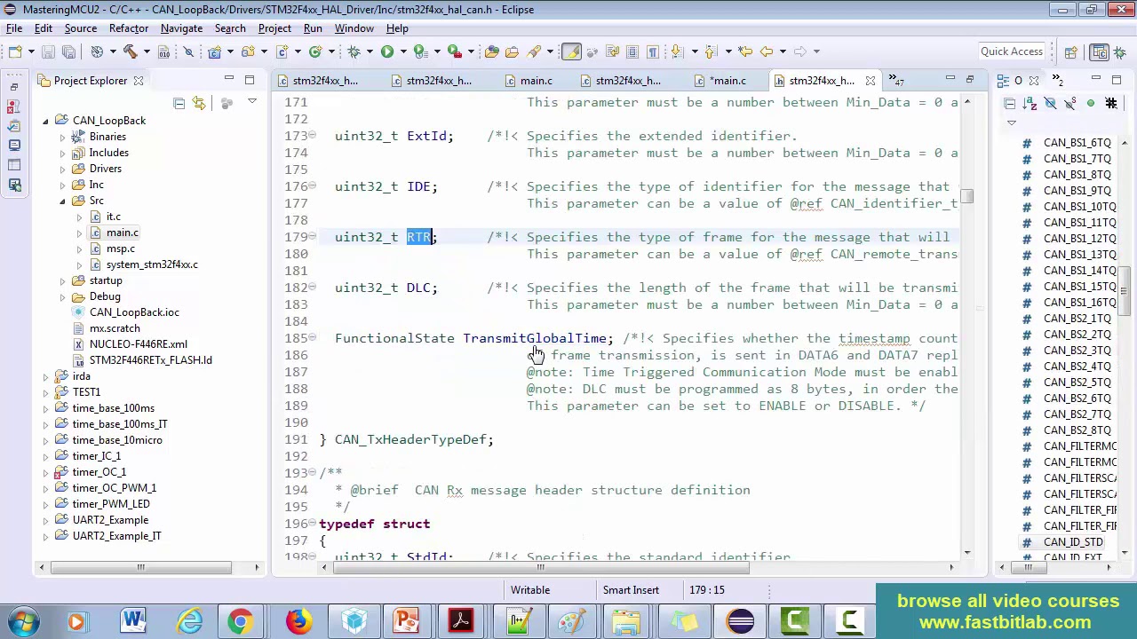
The CAN bus is a communication standard that is commonly used in automotive applications. It is used to transmit data between vehicles and other low-speed devices such as sensor nodes. The data transmitted is encoded with a digital signal, known as CAN, and includes several components. The CAN message itself is composed of four major components: the Data Length Code (DLC), the Extended Identifier (EDI), and the Remote Transmission Request (RTR). Each of these components has its own role in determining the format and the content of the CAN message.
It reduces wiring
The CAN bus is a standardized way of communicating with your car. It reduces wiring and complexity. In addition, it reduces the need for custom wire harnesses. The CAN bus mechanical standard consists of male and female D-sub connectors. The male connector receives power from the bus while the female connector receives the same energy from the bus. Adopting this standard will avoid the need for custom splitters or wire harnesses that join conductors outside the bus node. Nonstandard wire harnesses will reduce bus reliability, eliminate cable interchangeability, and increase cost.
It is flexible
If you want to learn how to program CAN buses, you may want to purchase a can bus programming tutorial. These tutorials can be very helpful in getting started with this powerful technology. They will teach you the ins and outs of this new type of bus, which is used in many modern vehicles. You can learn more about can bus topology, programming, and testing. These tutorials will help you get started with this powerful technology and keep you on the road as a successful programmer.
It is standardized
The CAN bus is a standard for communication between electronic devices. There are different types of devices connected to it, including vehicles. CAN uses bit-wise arbitration for access control and defines four message types. Each message carries an identification number tagged with its priority. This standardized bus has a simple yet elaborate error handling and confinement scheme. The basic concepts of CAN bus programming are explained in this tutorial.
It is compatible with Arduino
What is “It is compatible with Arduino”? Quite a few things, really. First of all, it means that the device supports the Arduino IDE. Most units have Atmel processors, though some are made by other manufacturers. Most boards are compatible with Arduino because third-party developers have created them and have added the IDE. However, some of these boards may not come with instructions and differ from the original board’s design.
It is a low-speed protocol
CAN is a wireless protocol that is commonly used by automobiles. This protocol allows vehicles to communicate with each other and can be used to monitor various parameters. CAN is comprised of two lines, CAN_H and CAN_L. The voltage on these lines is determined by the CAN controller and is used to send and receive data. The CAN bus standard has 5 mechanisms that detect errors. They include bit stuffing, bit monitoring, frame check, and cyclic redundancy check.
It is synchronized
The CAN specification defines the bits used to communicate in a CAN network. There are four segments, each containing a programmable number of time quanta. Each segment consists of two components: a CAN controller system clock and a Baud Rate Prescaler. Typically, a system clock is equal to fosc. CAN controllers measure and adjust phase buffer lengths to compensate for signal propagation delays within receiver/transmitter circuits.

